N228D02 2-Channel RS232 Relay Board


N228D02 2-Channel RS232 Relay Board
Variants2
| Voltage | Availability | Price incl. VAT | Quantity (ks) | |||
|---|---|---|---|---|---|---|
| 12V | in stock | 8,20 EUR | ||||
| 24V | Out of Stock Watch availability | 8,20 EUR | Demand |
2-Channel RS232 Relay Board DC 12V/24V for PLC, Motor, LED, PTZ Control
The 2-channel RS232 Relay Board is a compact and versatile module designed for industrial control applications, such as PLC systems, motors, LED lighting, PTZ camera controls, and other automation tasks.
It operates on DC 12V or 24V and provides RS232 DB9 serial communication, supporting multiple control modes, including self-locking, momentary, and interlock modes.
The module features relay output isolation for stable and safe operation and includes status and power indicators for clear monitoring.
This relay board is ideal for integration with industrial equipment and automation projects requiring reliable serial-controlled switching.
Specifications:
-
Model: N228D02
-
Working Voltage: DC 12V / 24V
-
Current Consumption:
-
Standby: 12 mA
-
1 Relay Active: 40 mA
-
2 Relays Active: 67 mA
-
-
Relay Channels: 2
-
Interface: RS232 DB9 serial port
-
Baud Rate: 9600 bps
-
Control Commands: Supported (via provided command set)
-
Operating Modes:
-
Self-locking mode (toggle relay state)
-
Momentary mode (200 ms pulse)
-
Interlock mode (one relay active, others off)
-
Individual or multiple relay control
-
-
Indicators: Relay status LED, Power LED
-
Isolation: Relay output isolation
-
Functions: Jog control (temporary activation and auto-off)
-
Dimensions: 68 × 45 × 17 mm
-
Weight: 40.3 g
Package Includes:
-
1 × 2-channel DC 12V/24V RS232 relay module
Instructions for Use
-
Connect the controller to your PC using a USB-to-RS232 module.
-
Open a serial port debugging tool on the PC.
-
Configure the connection settings as follows:
-
Port: Select the correct COM port for your device
-
Baud Rate: 9600
-
Parity: None
-
Data Bits: 8
-
Stop Bits: 1
-
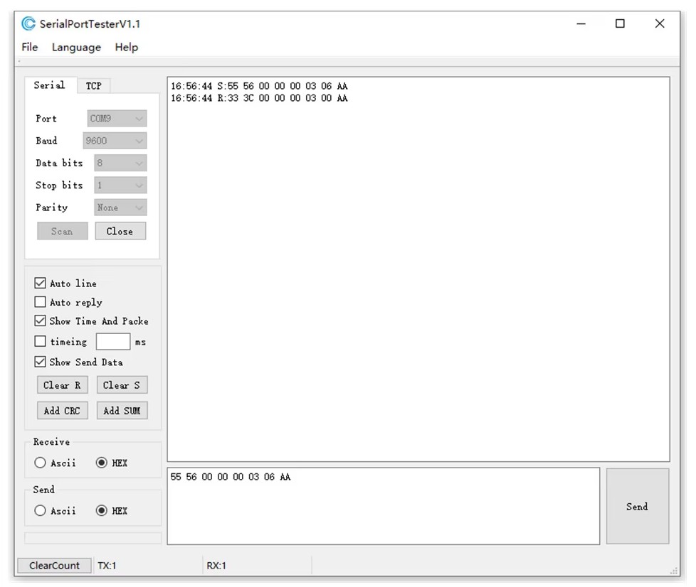
Example:
To turn on all relays, send the following command:55 56 00 00 00 03 06 AA
Explanation of the command:
-
0x5556– Frame header -
0x000000– Reserved bytes -
0xFF– All relays selected -
0x06– Command for multiple relays on/off operation -
0xAA– Terminator (end of the command)
Once the command is sent, all relays will be activated, as shown in the illustration below.
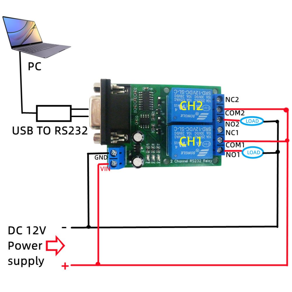
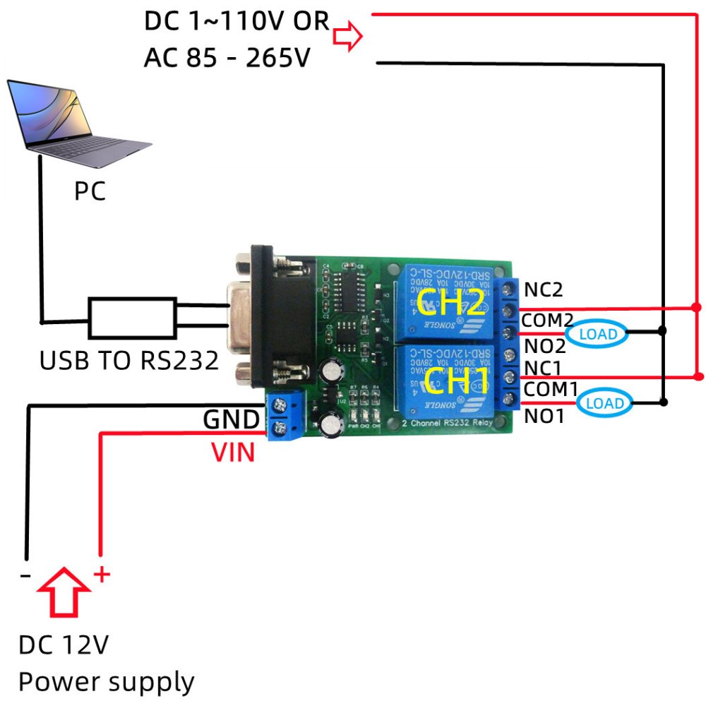
Wiring Diagram